Generating Circuit Diagrams automatically
Circuit diagrams for substations, power plants or cable distributors can be generated automatically using the ITS Circuit Diagram Generator. These diagrams are created within the sector-specific data model for electricity. Furthermore, the solution offers various editing tools, for example for transforming a single busbar system into a double busbar system.
- Optimal circuit diagram generation
- For all voltage levels i.e. low, high and medium
- Complex plants are created using a flexible configuration
- Editing functions
- Easy visualisation for switching status
Product Description
ITS Circuit Diagram Generator
The ITS Circuit Diagram Generator creates a standard circuit diagram for medium and low voltage transformer stations, plants or cable distributors based on specific parameters. Thus, it replaces prototype functionalities of the sector-specific module for electricity and spares users from having to maintain templates for different types of power stations and cable distributors.
Functions
After generating a circuit diagram, geometries of corresponding connection points are automatically created and added to the detailed plan. They can then be positioned at the correct cable end using standard Smallworld GIS functions. This reduces editing time to a minimum.
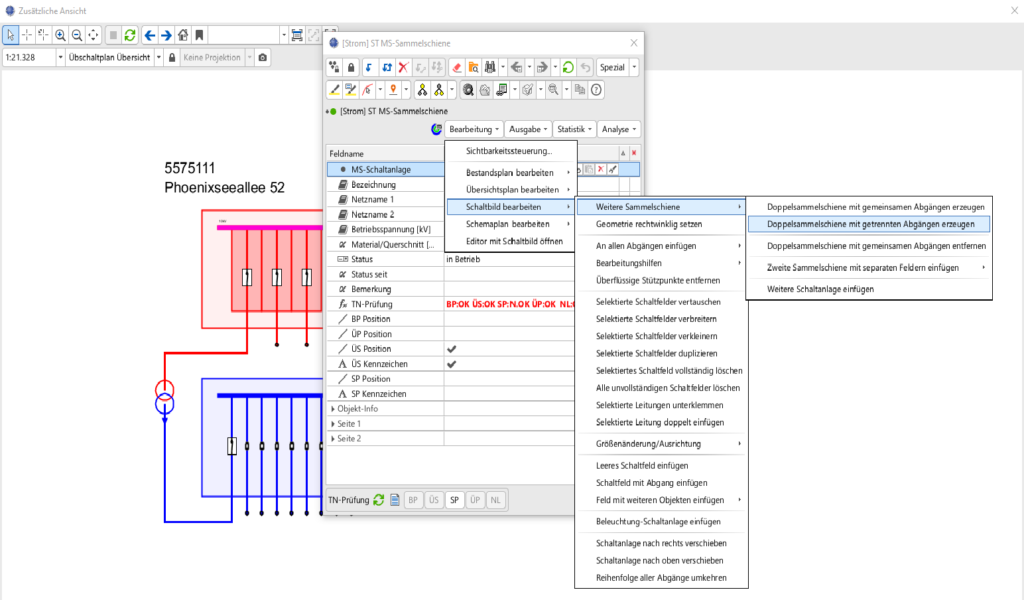
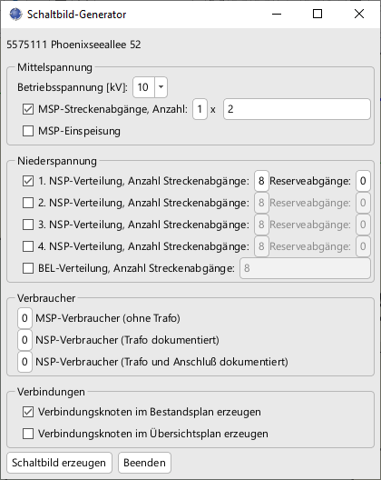
Generation
The ITS Circuit Diagram Generator produces a high or medium voltage distributor and up to two low voltage distributors as well as a lighting distributor. Furthermore, medium voltage supply and medium and low voltage end users can be documented. For existing circuit diagrams, functions are available to, for example, convert basic busbar systems into a double busbar system via the click of a button. This simplifies editing work in circuit diagrams.
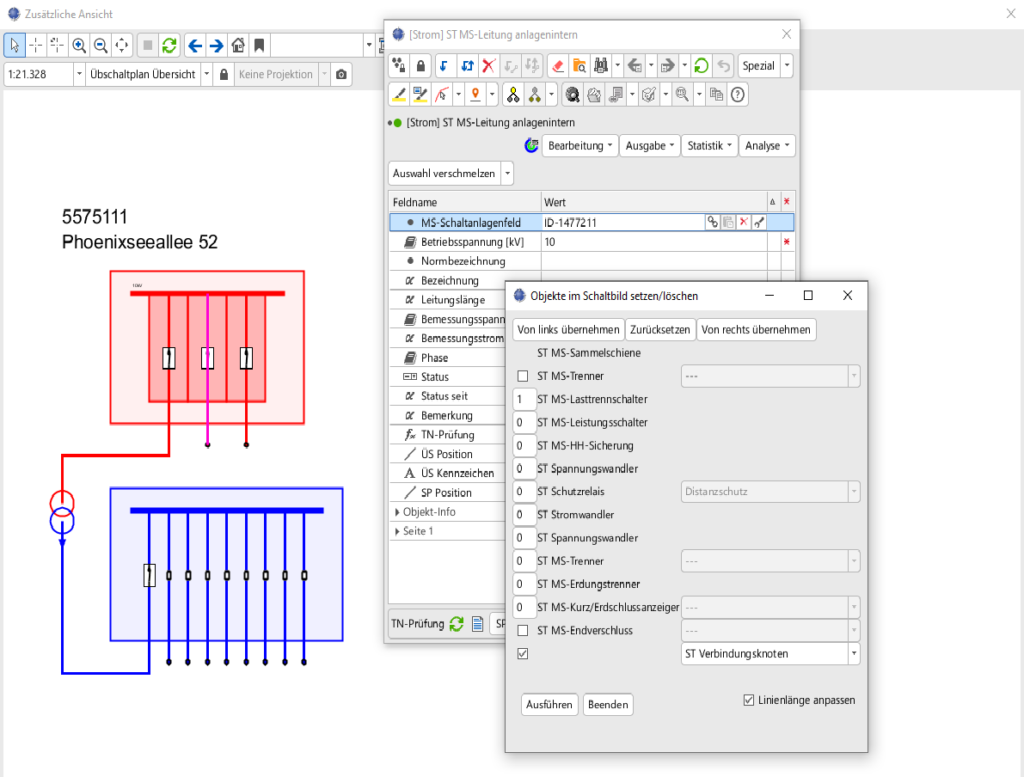
Editing Circuit Diagrams
Cables can be inserted into the circuit diagram without having to open editors for transformer stations, power plants or cable ditributors. Editing rules for generating these cables are applied automatically. In addition, attribute data for individual components of the circuit diagram can be inserted by extracting this information from the detailed or overview map.